Air Flow Straightener, Air Flow Profiler, and Air Flow Conditioner - What is the difference?
When measuring the flow of air or gas in a duct or pipe, accuracy is dependent on the type of device used to make the measurement, but is very dependent on the flow profile in the duct or pipe. For example, if the flow in the duct or pipe is turbulent, many types of flow measurement devices will not even be able to measure the flow or have such an error you would be better off not having the measurement at all. Here we will look further into turbulence and ways to minimize or eliminate it so that an accurate air flow measurement can be made.
What is Turbulence?
Turbulence can come in many forms, for example the flow could be spinning in the duct (cyclonic flow), or the flow could be going in the opposite direction than it is supposed to be going (reverse flow), or it can be off to one side or even angular (not parallel to the center-line of the duct or pipe). When a flow sensor, averaging pitot tube, thermal mass sensor (thermal dispersion), venturi, or even an orifice plate is used in flow conditions that are turbulent, the devices cannot possibly perform as designed, because the design of these types of air or gas flow measurement devices requires the flow to be uniform or "laminar". Uniform or Laminar Flow is when the flow is parallel to the center-line of the duct and the velocity is equal across the cross-section of the duct. This is the "perfect world".
So what causes turbulence in a duct or pipe?
Turbulence is caused by changes in the duct shape, obstructions, or other pieces of equipment. A simple change in the duct like a bend will cause the flow to change its profile. For instance, right after a 90 degree bend, the flow will impact the outer radius, start to spin, and hug the outer wall. When the duct configuration calls for a tee or take-off, the flow profile will change because some of the flow will want to not change direction and some will have to change direct, which will cause some of the flow to even reverse direction, creating pockets of very turbulent flow. In large ducts where the duct wall must be stiffened or supported by structural steel, the flow around these support will change the flow profile and create turbulence right after the obstruction. Some of the worst turbulence is caused by modulating dampers in a duct. As the damper is adjusted, the flow profile is changed significantly and will worsen as the damper's louvers or blade is closed. And then there is the flow on the outlet of a fan, don't get me started on discussing turbulence at this point in a process.
Typical Flow Turbulence Caused by a Louvre Damper
What is Turbulence?
Turbulence can come in many forms, for example the flow could be spinning in the duct (cyclonic flow), or the flow could be going in the opposite direction than it is supposed to be going (reverse flow), or it can be off to one side or even angular (not parallel to the center-line of the duct or pipe). When a flow sensor, averaging pitot tube, thermal mass sensor (thermal dispersion), venturi, or even an orifice plate is used in flow conditions that are turbulent, the devices cannot possibly perform as designed, because the design of these types of air or gas flow measurement devices requires the flow to be uniform or "laminar". Uniform or Laminar Flow is when the flow is parallel to the center-line of the duct and the velocity is equal across the cross-section of the duct. This is the "perfect world".
So what causes turbulence in a duct or pipe?
Turbulence is caused by changes in the duct shape, obstructions, or other pieces of equipment. A simple change in the duct like a bend will cause the flow to change its profile. For instance, right after a 90 degree bend, the flow will impact the outer radius, start to spin, and hug the outer wall. When the duct configuration calls for a tee or take-off, the flow profile will change because some of the flow will want to not change direction and some will have to change direct, which will cause some of the flow to even reverse direction, creating pockets of very turbulent flow. In large ducts where the duct wall must be stiffened or supported by structural steel, the flow around these support will change the flow profile and create turbulence right after the obstruction. Some of the worst turbulence is caused by modulating dampers in a duct. As the damper is adjusted, the flow profile is changed significantly and will worsen as the damper's louvers or blade is closed. And then there is the flow on the outlet of a fan, don't get me started on discussing turbulence at this point in a process.
Typical Flow Turbulence After a Bend
Typical Flow Turbulence Caused by a Tee or Duct Take-off
Typical Flow Turbulence Caused by Internal Duct Obstructions
Typical Flow Turbulence Caused by a Louvre Damper
So now that we have a better idea of what turbulence is and where it might be located, it is easy to see why putting a flow measurement sensor in a turbulent area will cause inaccuracy. The big question now, is what to do about it? The best solution is to put the sensor where there is no turbulence, but this may require many lengths of straight runs in order to get the flow profile to return to a Uniform or Laminar state.
The Old Standby Solution - Perf Plate or Honeycomb Flow Straighteners
For years the only solution when the straight runs were not available, which is the case in larger diameter ducts, was to use a flow straightener like a perf plate or honeycomb. The Straighteners job was to do just that, straighten out the flow pattern. The way this is done was to restrict the flow in the duct in a way to force it through much smaller openings. These can be holes in a plate or actual fins or restricting sections made from thin metal. The major drawback from this straightener is that in order to really straighten the flow, these must be relatively small openings, so there is a lot of resistance to flow that is created. This resistance to flow causes back pressure that can affect the ability of the system to maintain the desired flow. Unrecoverable loss of the pressure will result in dramatic changes in the overall system. The other thing is that these devices will not fix issues where the flow is reversing or where it is not equal across the cross section of the duct. Flow hugging the outer wall will still continue to hug the outer wall, but may actually begin to reverse since all that flow is being forces through the small openings. The devices are also not very robust devices, and can easily break or become plugged. Typically a flow measurement sensor is placed after the straightener, trying to take advantage of any flow straightening that occurs.
The Next Best Thing - Nozzles and Venturi Flow Profilers
The flow nozzle or venturi devices would be the next best thing to the flow straightener, having a section where the diameter of the duct is restricted down or nozzled down to a smaller diameter. This nozzling affect forces the flow to speed up through the smaller section, relieving issues like reverse flow and uneven flow across the duct cross section. The draw back to these devices is that the ratio of the duct area to the area of the reduced section is very high. This ratio is known as the beta ratio. With these types of beta ratio devices however, cyclonic or spinning flow is not corrected and the large change in diameter is done over a short length making an abrupt change in the flow pattern. This type of device also has a very large unrecoverable pressure loss potential, so recovery sections are usually used to try to reduce this pressure loss. However, this section requires a very large length of duct. Typically there are pressure taps on the inlet and throat section after the diameter change, where the differential pressure is measured to provide the flow measurement.
The Best Solution is Here! The High Beta from Eastern Instruments
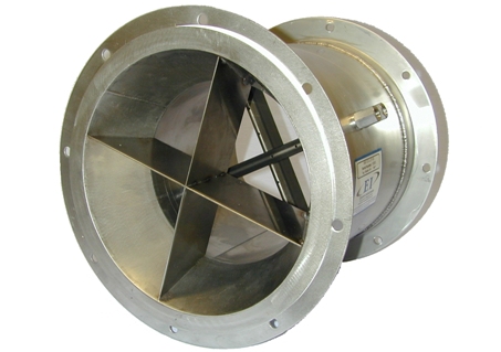
The best solution would be a flow conditioner that eliminates cyclonic flow, elminates reverse flow, profiles the flow evenly across the duct, and does not require a large length of duct or create back pressure and large unrecoverable pressure loss. The High Beta from Eastern Instruments is exactly that device! Its converging section with integral straightening vanes lead to a section of duct with our VAP³ Velocity Averaging Pitot Tubes, where a Uniform or Laminar Flow is created with almost no required upstream straight duct runs. The turbulent flow is directed through the converging section where the straightening vanes break up flow issues, while not restricting the flow causing back pressure. The straightening vanes are a structural part of the device, so they are very robust and will not break off in the flow stream. The smaller diameter duct section, call the throat, is designed such that the beta ratio is moderate, much higher than the venturi, allowing the flow to be conditioned without causing a high unrecoverable pressure loss, and no recovery section is required!
The High Beta Process Flow Element comes in low pressure and high pressure models in various standard diameters. The external spool or duct sections can be painted carbon steel or stainless steel depending on the requirements of the application. The integral VAP³ Pitots measure this conditioned flow with unparalleled accuracy.
 |
| High Beta Process Flow Element (HBP) |
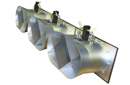
For large ducts, square/rectangular duct and Combustion applications, the High Beta Engineered Flow Element can be manufactured to fit the exact needs of the customer and application. It can be made in a wide array of configurations and materials as needed.
 |
| High Beta Engineered Flow Element (HBE) |
For more information about these devices and to talk to a Sales Engineer about your application, please contact Eastern Instruments at 910-392-2490. You can send and email to sales@easterninstruments.com if you would like to receive more information via email or visit our website at easterninstruments.com.
